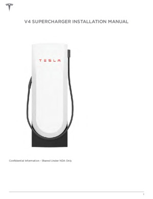
V4 SUPERCHARGER INSTALLATION MANUAL Confidential Information - Shared Under NDA Only 1 ABOUT THIS MANUAL This manual contains specifications and procedures required for the successful installation of the Tesla V4 Supercharger. READ THIS ENTIRE DOCUMENT BEFORE INSTALLING OR WORKING WITH THE SUPERCHARGER SYSTEM. Failure to do so or to follow any of the instructions or warnings in this document can result in electrical shock, serious injury, death, or damage to one or more parts of the Supercharger system, potentially rendering it inoperable. All specifications and descriptions contained in this document are verified to be accurate at the time of printing. However, because continuous improvement is a goal at Tesla, we reserve the right to make product or documentation modifications at any time, with or without notice. 2012-2023 TESLA, INC. All rights reserved. All information in this document is subject to copyright and other intellectual property rights of Tesla, Inc. and its licensors. This material may not be modified, reproduced, or copied, in whole or in part, without the prior written permission of Tesla, Inc. and its licensors. Additional information is available upon request. The following are trademarks or registered trademarks of Tesla, Inc. in the United States and other countries:
MADE IN THE USA 2 ABOUT THIS MANUAL DISCLAIMER This document is updated as often as possible, but some sections may become outdated as a result of rapid, unforeseen changes in the service development process. This manual communicates Notes, Cautions, and Warnings with the following icons and definitions. NOTE: Indicates an important step or tip that leads to best results, but is not necessarily related to physical safety or equipment damage. CAUTION: Indicates a hazardous situation which, if not avoided, may result in damage to equipment, tooling, or other hardware. WARNING: Indicates a hazardous situation which, if not avoided, may result in bodily injury or death. 3 FCC Regulations:
This device complies with part 15 of the FCC Rules. Operation is subject to the following two conditions: (1) This device may not cause harmful interference, and (2) this device must accept any interference received, including interference that may cause undesired operation. Changes or modifications not expressly approved by the party responsible for compliance could void the users authority to operate the equipment. This equipment has been tested and found to comply with the limits for a Class B digital device, pursuant to part 15 of the FCC Rules. These limits are designed to provide reasonable protection against harmful interference in a residential installation. This equipment generates, uses and can radiate radio frequency energy and, if not installed and used in accordance with the instructions, may cause harmful interference to radio communications. However, there is no guarantee that interference will not occur in a particular installation. If this equipment does cause harmful interference to radio or television reception, which can be determined by turning the equipment off and on, the user is encouraged to try to correct the interference by one or more of the following measures:
Reorient or relocate the receiving antenna. Increase the separation between the equipment and receiver. Connect the equipment into an outlet on a circuit different from that to which the receiver is connected. Consult the dealer or an experienced radio/TV technician for help. RF Exposure Information (MPE) This device has been tested and meets applicable limits for Radio Frequency (RF) exposure. This equipment should be installed and operated with minimum distance 20 cm between the radiator & your body. IC Regulations:
CAN ICES-3(B)/NMB-3(B) This device contains licence-exempt transmitter(s)/receiver(s) that comply with Innovation, Science and Economic Development Canadas licence-exempt RSS(s). Operation is subject to the following two conditions: (1) This device may not cause interference. (2) This device must accept any interference, including interference that may cause undesired operation of the device. Lmetteur/rcepteur exempt de licence contenu dans le prsent appareil est conforme aux CNR dInnovation, Sciences et Dveloppement conomique Canada applicables aux appareils radio exempts de licence. Lexploitation est autorise aux deux conditions suivantes : 1) Lappareil ne doit pas produire de brouillage; 2) Lappareil doit accepter tout brouillage radiolectrique subi, mme si le brouillage est susceptible den compromettre le fonctionnement. RF Exposure Information (MPE) This device has been tested and meets applicable limits for Radio Frequency (RF) exposure. This equipment should be installed and operated with minimum distance 20 cm between the radiator & your body. Informations d'exposition RF (MPE) Cet appareil a t test et rpond aux limites applicables en matire d'exposition aux radiofrquences (RF). Cet quipement doit tre install et utilis avec une distance minimale de 20 cm entre le radiateur et votre corps. COMPLIANCE INFORMATION The V4 Supercharger system is classified as the following for the specified categories:
Category V4 Supercharger Classification Characteristics of power supply input Electric Vehicle supply equipment (cabinet) connected to an AC supply network Electrical connection method Permanently connected Characteristics of power supply output DC Electric Vehicle supply equipment Normal environmental conditions Outdoor use Access Mounting method Equipment for locations with restricted access Stationary equipment; floor/ground mounted Protection against electric shock Class I equipment Charging mode Mode 4 4 PART NUMBERS Part Name Part Number Charge Post Skin Charge Post Side Covers 1671197-00-A 1863921-00-A NOTE: Please find the V4 Supercharger Post Datasheet linked here. 5 STEP 1: REMOVING THE CHARGE POST SKINS 1. Remove the cosmetic cover over the cable attachment by sliding it out. 2. Use a small flat screwdriver to remove the cover over the charge post lid bolts on both sides of the Charge Post. 3. Use a torque driver to remove the two T27 Torx bolts securing the charge post lid to the charge post. Repeat for the other side of the charge post. Store the side covers and bolts in a plastic bag. 6 STEP 1: REMOVING THE CHARGE POST SKINS Part Numbers on page 5 4. Remove the charge post lid by lifting it upward. Store the charge post lid in a dry and clean location. Ensure that the sealing gasket on the bottom of the charge post lid does not get damaged. 7 STEP 1: REMOVING THE CHARGE POST SKINS 5. Grip the charge post skin on the left and right with both hands and slide it straight up (1). Pull the skin outward to release it from the post (2). 8 STEP 1: REMOVING THE CHARGE POST SKINS a. Review the inside of the charge post and note the locations of the metal studs that mate with the teardrop-shaped holes in the bollard. 6. Mark the inside of the skin (1A, 1B, etc). CAUTION: Since the charge post skins are very large and are a solid piece, they can easily get caught by the wind. Take extra caution when removing and storing the skins to avoid damages. CAUTION: Store the skin in a clean and dry place and make sure it does not get damaged or scratched. 9 STEP 2: MOUNTING THE CHARGE POST 1. Use a torque driver to remove the 4 nuts securing the charge post to the base of the pallet. 2. Insert four M10 lifting eyes into the four tapped holes on the bollards. CAUTION: Avoid cross-threading the lifting eyes. WARNING: Ensure that both skins are removed before lifting. The V4 charge post weighs approximately 90kg (200lbs) and only 66kg without the skins. 10 STEP 2: MOUNTING THE CHARGE POST 3. Inspect for leaking Heat Transfer Fluid. NOTE: Note that the HTF is transparent and contains 50% ethylene glycol by volume. 4. Inspect the charge post skins for any damage or breakage and report as needed. NOTE: Part Numbers on page 5 NOTE: The front and rear skins are identical. 5. Identify the charge post's anchor locations (which are identical to the V3 charge post locations):
11 STEP 2: MOUNTING THE CHARGE POST 6. Position the charge post so that the cable terminus is closer to the center of the charging stall, and that the charging cable is draped on the side of the charge post facing the stall that is served by that charge post . NOTE: The image on the left shows the Service Access side of the charge post. The image on the right shows the Non-Service Access side of the charge post. 12 STEP 2: MOUNTING THE CHARGE POST 7. Install a leveling nut and washer on each anchor, ensuring that the top of the installed washers has a minimum height between 26 and 28 mm above the concrete surface. Anchors must extend at least 100 mm (4") above the foundation surface. If anchors are not supplied by Tesla, ensure that the anchors are long enough to achieve embedment in accordance with the site drawings or anchor manufacturer specifications. Level the charging post if needed. 13 STEP 2: MOUNTING THE CHARGE POST 8. Secure the charge post to the base by installing an additional washer and nut on each anchor and tightening them according to site design drawing specification. 14 STEP 3: WIRING THE CHARGE POST 1. Disconnect the harness for the front logo light by pushing the tab inward (1), then pulling the terminal outward (2). This harness may come from the factory already disconnected. 15 STEP 3: WIRING THE CHARGE POST 2. Open the junction box by turning the two -turn latches on the door clockwise. WARNING: Wear head protection gear as the junction box has sharp corners. CAUTION: Close the door to the junction box when it is not being worked on or when it is raining or snowing. CAUTION: Use a tent whenever it is raining or snowing. CAUTION: Do not leave the junction box door open if it is windy; the door may swing closed and pose a hazard. 16 STEP 3: WIRING THE CHARGE POST 3. You can remove the door to the junction box while you are working on it by pulling the hinge pins upward. 17 STEP 3: WIRING THE CHARGE POST 4. Inspect the termination block and identify the positive and negative MVDC termination points, the LV termination block and the MVDC and Comm Cable entry point. NOTE: Apply anti-oxidant paste to all aluminum wires. 1 2 3 4 Positive Negative LV & Comm Cable Termination Block MVDC Entry 5. Choose one of the following options:
If the power conductors are going to be pulled before the charge post is landed: Use a snipping tool to cut the power conductors so that at least 175 cm (69") of the wires extend from the foundation surface. If the power conductors are going to be pulled after the charge post is landed: Skip this step. NOTE: The equipotential bonding sits lower and can be cut to 140cm (55"). 18 STEP 3: WIRING THE CHARGE POST 19 STEP 3: WIRING THE CHARGE POST 6. Inspect the V4 Comm Cable which integrates both signal and power wires needed for charge post operations. The drain, black, white, and orange wires are terminated in the smaller connectors (in that order from left to right). Bare: Drain wire Black and white pair: CAN communication Orange: Enable line From left to right: Drain - Black - White - Orange The red and grey pair of 8AWG (10mm2) wires are terminated in the two larger connectors at the left of the LV termination block. Red/Grey pair: 24V Power 20 STEP 3: WIRING THE CHARGE POST 7. Terminate the PE conductors by routing them into the charge post so there is a service loop of at least an additional 300 mm. 8. Mark the required length of the wires and cut and strip 25mm of insulation. Apply anti-oxidation compound to aluminum wires. 21 STEP 3: WIRING THE CHARGE POST 9. Use a 5/16 Hex drive torque tool to tighten the lug screws to 30Nm. NOTE: Do not apply torque marks to the lugs. 22 STEP 3: WIRING THE CHARGE POST 10. Push the signal cable up through the gland nut to terminate the LV and Comms conductors in the following steps. 11. Strip approximately 300mm of the purple outer jacket and the braided shield. 23 STEP 3: WIRING THE CHARGE POST 12. Wrap the entire length of the drain wire in green electrical tape. Apply heat shrink wrap over the transition point where the outer jacket was removed NOTE: If the signal cable includes an additional 2-pair cable inside, tape off the ends of the 2-
pair cable and coil up the 300 mm length and tuck it out of the way. 13. Tighten the gland nut to secure the signal cable. 14. Terminate the pair of red/grey 8AWG (10mm2) wires into the two large terminals at the right of the LV termination block, depressing the lever to engage the connector once the conductor is inserted. 24 STEP 3: WIRING THE CHARGE POST Press down the levers to engage the connectors. 15. Use ferrules to terminate the drain, black, white, and orange wires into the small terminals. Insert the wires and depress the levers to engage the terminal. Gently pull on each wire to ensure it is securely connected. 25 STEP 3: WIRING THE CHARGE POST Press down the levers to engage the connectors. 16. Route the MVDC conductors from the conduit stub-up beside and behind the radiator/fan assembly. 26 STEP 3: WIRING THE CHARGE POST 17. Align the MVDC conductors outside of the junction box to mark the required length and cut them to length. Strip 35mm of insulation. 18. Terminate the MVDC conductors into the back lugs by pushing the two longer conductors (one positive and one negative) up through the rear openings in the rubber seal. Continue pushing the conductors up into the two upper lugs, using wire-pulling lubricant as needed. Apply anti-oxidation compound to aluminum wires. 27 STEP 3: WIRING THE CHARGE POST 19. Use an 8 mm Hex drive with a 150 mm extension to fasten the lug set screws. Torque the lug set screws to 60Nm. Do not apply torque marks to the lugs. 20. Terminate the MVDC conductors into the front lugs by pushing the two shorter conductors (one positive and one negative) up through the front openings in the rubber seal. Continue pushing the conductors up into the two lower lugs, using wire-pulling lubricant as needed. Apply anti-oxidation compound to aluminum wires. 21. Use an 8 mm Hex drive with a 150 mm extension to fasten the lug set screws. Torque the lug set screws to 60Nm. Do not apply torque marks to the lugs. 28 STEP 4: CLOSING THE CHARGE POST 1. Position the junction box cover on the junction box. Secure the junction box cover by turning the two latches turn counter-clockwise. Leave the front logo light harness disconnected. 2. Position the charge post skin to the charge post by aligning the 14 metal studs on the charge post skin with the teardrop-shaped holes on the bollard and sliding it into place (1). Slide the charge post skin downward into place (2) until it secures to the charge post. 29 STEP 4: CLOSING THE CHARGE POST 30 STEP 4: CLOSING THE CHARGE POST 3. Secure the top cover to the charge post with 4 bolts using a T27 Torx driver. 4. Position the two side covers on either side of the charge post. Secure the side covers to the charge post by installing the bottom part of the covers first (1), then pushing the top part into place (2). 5. Use soap, water and rags to clean the charge post as needed. 31 DOCUMENT REVISION HISTORY DISCLAIMER This document is updated as often as possible, but some sections may become outdated as a result of rapid, unforeseen changes in the service development process. Date Changes 07/18/2023 Updated images and instructions based on the new charge post design throughout the manual. 04/10/2023 Initial release. Author nshafaei nshafaei 32
